Process plants are a family now
The water–steam side of a steam plant, from a brief to a P&ID, tags, routed pipe and a PCF per line, and where it stops.
 Nordform editorial · 4 min read
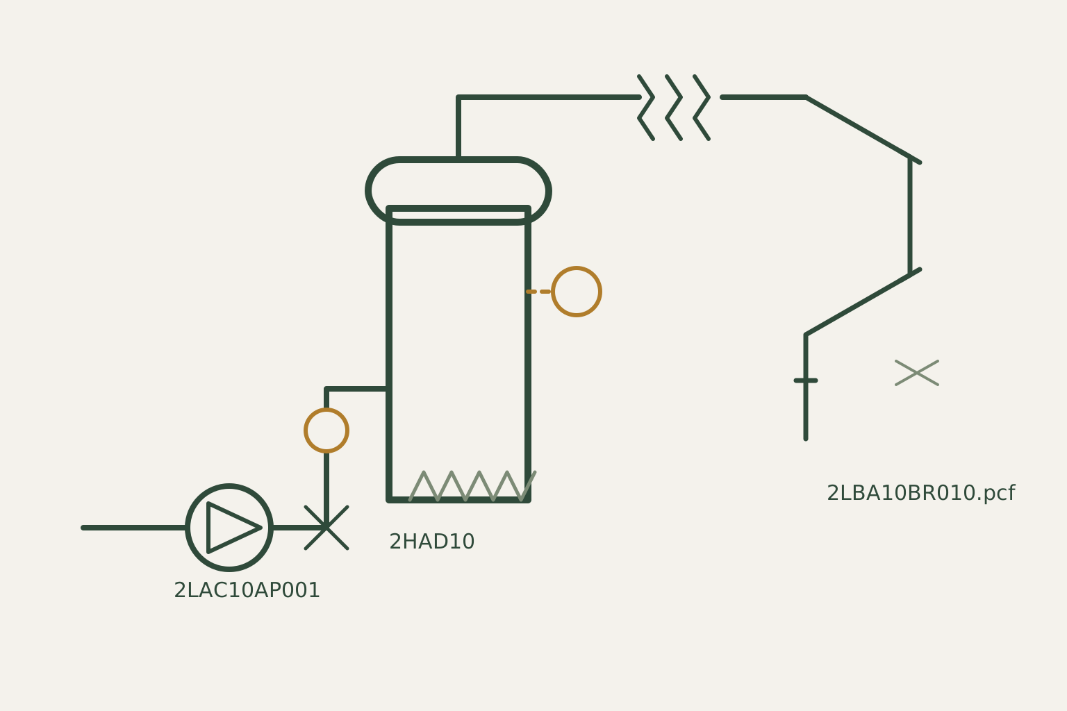
Until today a process plant in Nordform was a demo: a hydrogen-to-methane chain you could watch being routed. From today the water–steam side of a steam plant is also a family in the catalogue, next to pipe runs and electrical circuits. You choose a plant, answer four questions, and get drawings and files you can open in other tools.
It is a concept tool. Nothing it produces is sized, and none of it is for construction or operation. The rest of this post says what it does and where it stops.
What you get
You pick one of three plants: a boiler island between battery limits, a closed loop with a header, a heat consumer and the condensate return, or a worked example of a combined heat and power plant with a turbine and its bypass. You state a steam pressure, a steam temperature, the number of feedwater pumps and the main steam size.
From that the family makes:
- a P&ID, drawn from the process graph by named patterns;
- KKS-style tags for the equipment, lines, valves and measurements;
- a placement of the equipment in a row, with pipe routed between the nozzles;
- for every routed line, a Piping Component File (PCF) and an isometric;
- the tag list as a spreadsheet file, the process topology as SFILES 2.0, and the full list of findings.
The same inputs always give the same files.
What checks it
Each stage is checked by code that does not share its working with the code that made it. The patterns that draw the P&ID are found again by a separate check. The tags are judged by taking each tag apart and reading it against the code table. The piping is checked for continuity from the written file.
The PCF files of the worked example are also opened by pcf2iso, an open-source PCF tool we did not write. It reads every file back byte for byte, reports no problems, finds each line connected end to end, and computes the same cut lengths we do. That is the only part of this we call independently checked. Reading a file back with our own reader is a self-check and we do not count it.
Scope
- The tag table is one project's. The codes come from the coding guide of one Finnish power-plant project, published as a procurement attachment and transcribed by us, and every tag list names that source. An object the guide has no code for is left untagged and reported.
- The P&ID patterns are our own, and every drawing states their review status.
- The boiler rules come from one engineer's note. Eight rules about what a boiler P&ID should show are read over the model. Where the model carries no fact a rule needs, such as a safety valve or a burner, the rule is reported as not assessed.
- The worked example fails the feedwater rule. It has no check valve and isolation valve between the pumps and the drum, and the check reports exactly that.
- Pressure and temperature are recorded on each line. Wall thickness, rating and pipe class come from your engineer.
- Engineering stays with your engineer. Heat and mass balance, sizing, set pressures, stress, supports and hazard study sit outside the family, and fitting dimensions are assumed. The files say this in their own headers.
- It covers the water–steam side. Combustion, fuel, flue gas, chemical dosing, sampling, drains and vents are outside it.
If this is your field
The most useful thing you could send us is a correction: a tag we coded wrongly, a pattern that would not survive your review, or a project code list we could check ours against. Tell us what you need to see for a real project.